Bernoulli's Theorem Apparatus
DESCRIPTION
The equipment is designed and fabricated to demonstrate the Bernoulli's theorem. It consists of a test section made of acrylic. It has convergent and divergent sections. Pressure tappings are provided at different locations in convergent and divergent section. Present set-up is self contained water re-circulating unit, provided with a sump tank, centrifugal pump etc. An arrangement is done to conduct the experiment on different flow rates. Flow rate of water is measured with the help of measuring tank and stopwatch.

Impact Of Jet On Vanes Apparatus
DESCRIPTION
The Set-up consists of two sided clear fabr1catt0n. Water is fed through a nozzle and discharged vertically to strike a target carried on a stem, which extends through the cover. A weight carrier is mounted on the upper end of the stem. The dead weight of the moving parts is counter balanced by a Compression spring. The vertical force exerted on the target plate is measured by adding the weights supplied to the weight pan until the mark on the weight pan corresponds with the level gauge. A total of two targets are provided a flat plate and a hemispherical cup.

Venturi Meter & Orificemeter Apparatus
DESCRIPTION
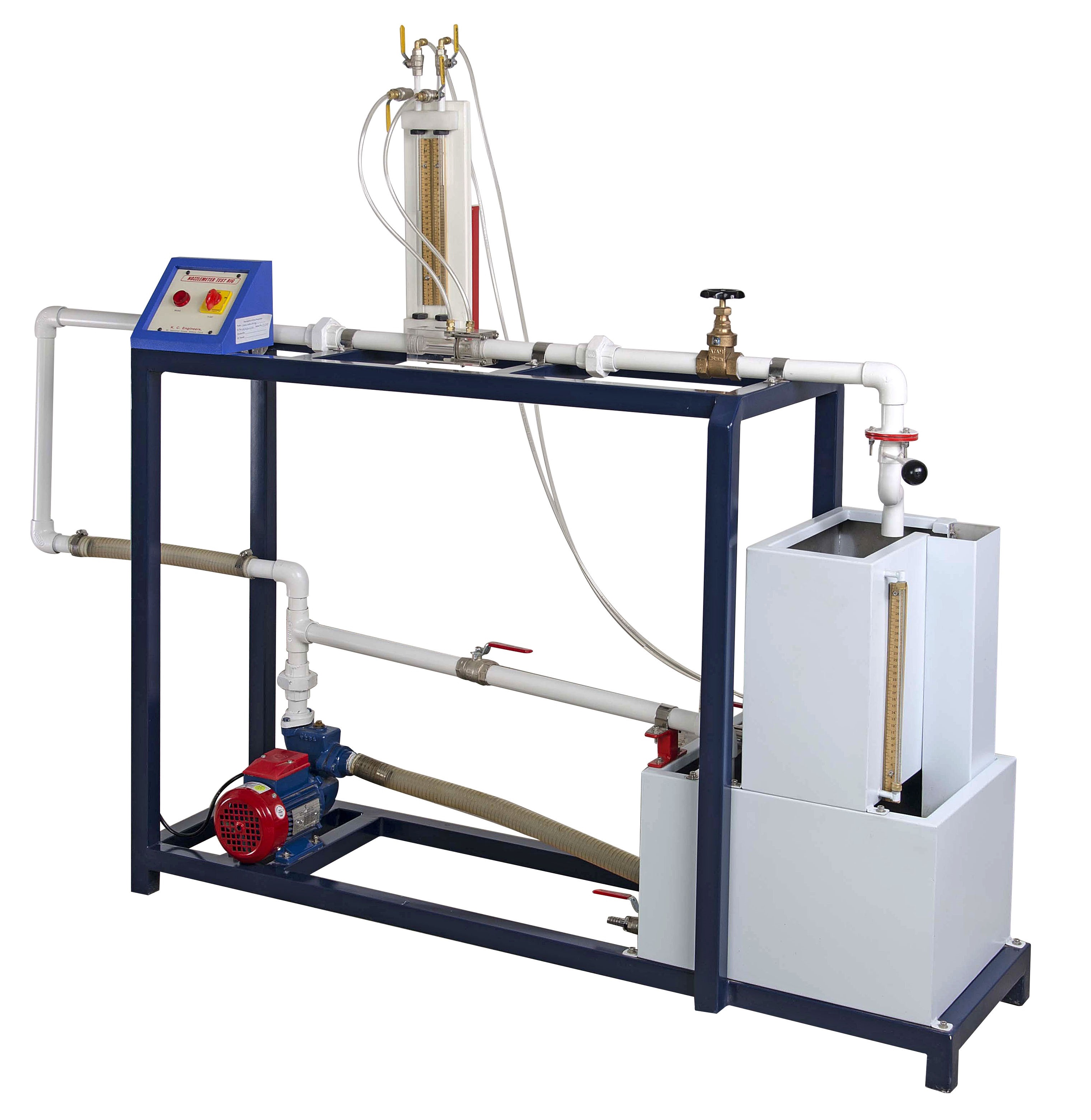
The apparatus consists of two pipelines emerging out from a common manifold. One pipeline contains a Venturimeter, second contains an Orifice. The pressure tapings from the Venturimeter and Orificemeter are taken to differential manometer to measure pressure difference. The Venturimeter and Orificemeter are connected in parallel and anyone of them can be put in operation by operating valves provided at the downstream. These valves can also regulate the flow. Present Set-up is self contained water re-circulating unit, provided with a sump tank and a centrifugal pump. Flow control valve and by-pass valve are fitted in water line to conduct the experiment on different flow rate. Flow rate of water is measured with the help of measuring tank and stop watch.

Pelton Wheel Turbine
DESCRIPTION
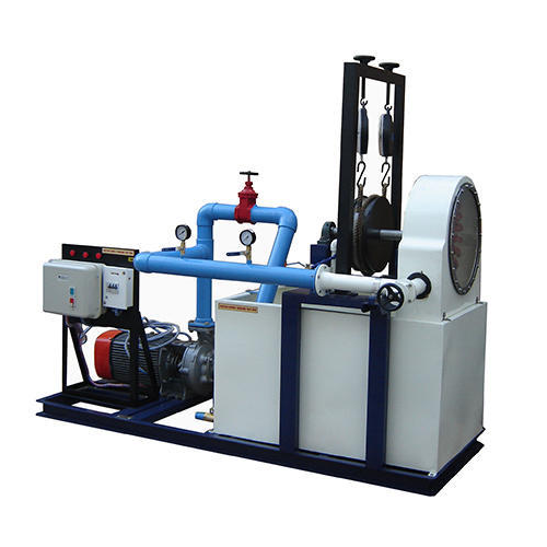
Pelton Wheel Turbine is only impulse water turbine, now in common use, named in the honor of Sir L.A. Pelton (l829· 1908) of California, USA. It is a tangential flow impulse turbine. The water strikes the buckets along the tangent of the runner. The energy available at the Inlet of the Turbine is only kinetic energy. The Pressure at the Inlet and Outlet of the atmospheric. This turbine is used for high heads. The Present Set-up consists of a runner. The buckets are mounted on the runner. The water is fed to the turbine through SS nozzle with a SS spear, by means of Centrifugal Pump, tangentially to the runner. Row of water into turbine is regulated by adjusting the spear position by the help of a given hand wheel. The runner is directly mounted on one end of a central SS shaft and other end is connected to a brake arrangement.

Francis Turbine Test Rig
DESCRIPTION
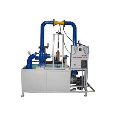
Francis Turbine is a reaction Turbine, which was developed by English born American Engineer Sir J.B. Francis. The water enters the turbine through the outer periphery of the runner in the radial direction and leaves the runner in axial direction and hence it is called a mixed flow turbine. As the water flows to the runner, a part of pressure energy goes on changing into kinetic energy. Thus, the water through the runner is under pressure. The runner is completely enclosed in air tight casing and runner is always full of water.
The present set-up consists of a runner. The water is fed to the turbine by means of centrifugal Pump, radially to the runner. The runner is directly mounted on one end of a central SS shaft and other end is connected to a brake arrangement.

Kaplan Turbine Test Rig
DESCRIPTION
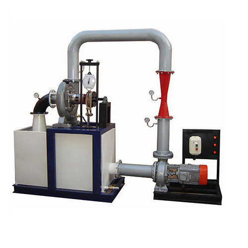
Kaplan Turbine is an axial flow reaction Turbine named in honor of Dr. B. Kaplan. a German Engineer. This turbine is suitable for low head. The power produced by a turbine is proportional to QH. As the head (H) decreases the J discharge (Q) must increase to produce the same power. The present Set-up consists of a scroll casing housing a runner. Water enters the turbine through the stationary guide vanes and passes through the runner axially. The runner has a hub and airfoil vanes, which are mounted on it. The water is fed to the turbine by means of Centrifugal Pump. The runner is directly mounted on one end of a central SS shaft and other end is connected to a brake arrangement. A transparent hollow cylinder made of acrylic is fitted in between the draught tube and the easing for observation of flow on to the airfoil vanes.
