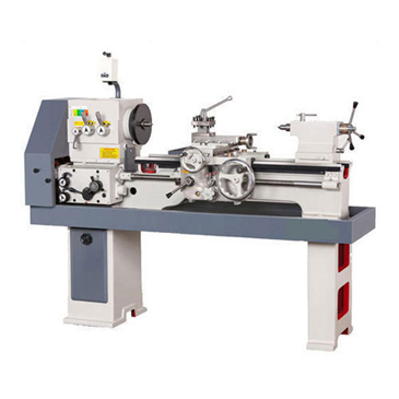
ALL GEARED LATHE
DESCRIPTION
All Geared Lathe Machine used for cutting materials and giving it shape. For increasing swiftness, it is efficiently designed. Lathe Machines are designed with efficient speed and dynamic spindle structure. Precise bed design effective performance.
All Geared Lathe Machines and have excellent technical team that provides guidance on technical aspects.
STANDARD ACCESSORIES
Flame Hardened bed ways
Chuck back plate 1 no
Centre adapter
Dead centres 2 nos
Tool Post Spanner
Motor pulley
Thread dial indicator
Change gear set - 1 (For metric and inch both)
Norton Gear Box
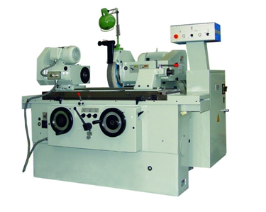
CYLINDRICAL GRINDING MACHINE
DESCRIPTION
Cylindrical Grinding Machine With high machining precision, the integral layout of machine tool is rational. Appearance is attractive, operating handles are centralized arranged and visualization, thus to make the machine easy to control and safe to operate.
A manual cylindrical grinder is designed to shape the outside of an object with a central axis of rotation such as a cylinder, ellipse, cam or crankshaft. The grinders in this category are controlled through manual or semi-automatic systems.
Cylindrical grinders have a heavy aged cast iron construction, that has been precision machined and hand scraped. The manual series has a hydro-dynamic spindle and a hydrostatic lubrication system on the table and wheelhead ways. With these special features, your grinders will give you many years of trouble-free operation and high accuracies.

UNIVERSAL RADIAL DRILLING MACHINE
A radial drilling machine or radial arm press is a geared drill head that is mounted on an arm assembly that can be moved around to the extent of its arm reach. The most important components are the arm, column, and the drill head. The drill head of the radial drilling machine can be moved, adjusted in height, and rotated. Aside from its compact design, the radial drill press is capable of positioning its drill head to the work piece through this radial arm mechanism. The tasks that a radial drilling machine can do include boring holes, countersinking, and grinding off small particles in masonry works.The radial drilling machine is intended for drilling medium to large and heavy work pieces.

PILLAR DRILLING MACHINE
DESCRIPTION
We provide wide range of machining components which are supportive in several industries to carry out multiple machining operations. Drilling remains one of the important machining aspects required in metal, automotive and similar industries and we provide high precision pillar drill machine to match accurate boring requisites. Our this tool is designed as per industrial standards and provided with rough construction to fulfil optimum machining performance expected in different industries. It is featured with easier operational modes at the same time can be depended on for accurate drilling. It is flawless in machining and stays durable in quality.
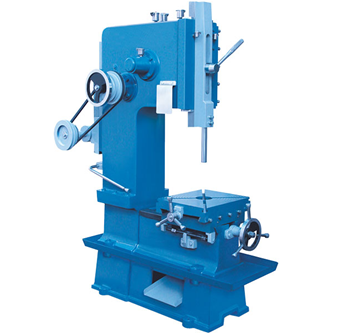
SLOTTING MACHINE
DESCRIPTION
The slotting machine is used for cutting grooves, keys and slotes of various shapes making regular and irregular surfaces both internal and external cutting internal and external gears and profiles The slotter machine can be used on any type of work where vertical tool movement is considered essential and advantageous.
The different types of slotting machines are:
1. Punch slotter: a heavy duty rigid machine designed for removing large amount of metal from large forgings or castings
2. Tool room slotter: a heavy machine which is designed to operate at high speeds. This machine takes light cuts and gives accurate finishing.
3. Production slotter: a heavy duty slotter consisting of heavy cast base and heavy frame, and is generally made in two parts.

GEAR HOBBING MACHINE
DESCRIPTION
Hobbing machines provide gear manufacturers a fast and accurate method for cutting parts. This is because of the generating nature of this particular cutting process. Gear hobbing is not a form cutting process, such as gashing or milling where the cutter is a conjugate form of the gear tooth. The hob generates a gear tooth profile by cutting several facets of each gear tooth profile through a synchronized rotation and feed of the work piece and cutter.

CNC TURNING MACHINE
Key Features
Rigid bed and single piece 30° slant saddle construction.
Rigid headstock & Heavy duty spindle.
High precision L.M. guide ways.
Bi-directional high speed servo turret.
Fast tool changing time just 0.5 sec.
Efficient chip disposal.
Tail stock with hydraulic quill.
Hydraulic chucking.
Auto and manual coolant system.
Electrical with quality devices & panel with A.C.
Centralized & programmable lubrication.

CNC MACHINING CENTRES
Key Features
Broad column structure and robust construction.
High dynamics structure and high acceleration upto 5m/sec2
Table with high load carrying capacity.
Wider Linear Motion guide ways.
High performance 10000rpm BT-40 ceramic bearing spindle for DM-version.
High Torque & High Power spindle motor for P-version.
Electricals with quality device & panel AC.
90° tilting operator panel.
Ergonomic design and improved operating condition.
Auto & manual coolant.
Efficient chip disposal and easy chip evacuation
Wide working area.
Centralized & programmable lubrication

VERTICAL MILLING MACHINE
DESCRIPTION
This tool is useful for accurately shaping metal and many solid materials. We supply manually operated, mechanically automated and digitally automated CNC milling instruments. Our tough and user friendly instruments can perform massive and trouble-free operations. It is mostly suitable for precise and assorted milling jobs. These tools ensure durability and reliability. Their versatile features and higher cutting capacity leads to better efficiency. These instruments are created using best quality components to meet maximum load conditions. They are economical and stable.

HORIZONTAL MILLING MACHINE
DESCRIPTION
This horizontal milling machine can be mounted with cylindrical milling cutter, angular milling cutter, formed cutter and rose cutter to machine all kinds of plane, level, groove and gear. Accessories such as universal milling head, swivel table and dividing head can be mounted on this horizontal milling machine to expand the range of applications;
The table of this universal knee type horizontal milling machine can swivel 45° left and right. Using a dividing head on the machine, all kinds of helical surfaces can be produced by swiveling the worktable to a certain angle;
Three-direction feed lead screws are trapezium lead screws;
If mounted with a digital readout, workpiece can be measured during milling to guarantee the machining quality of workpiece and reduce operator labor intensity;

INJECTION MOULDING MACHINE
DESCRIPTION
Injection molding machine molds can be fastened in either a horizontal or vertical position. The majority of machines are horizontally oriented, but vertical machines are used in some niche applications such as insert molding, allowing the machine to take advantage of gravity. Some vertical machines also do not require the mold to be fastened. There are many ways to fasten the tools to the platens, the most common being manual clamps (both halves are bolted to the platens); however, hydraulic clamps (chocks are used to hold the tool in place) and magnetic clamps are also used. The magnetic and hydraulic clamps are used where fast tool changes are required.
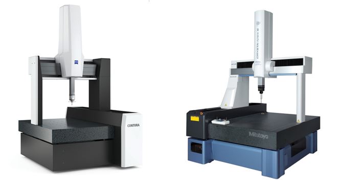
COORDINATE MEASURING MACHINE
Features
High-precision, self-adjusting air bearings on all axes
Lightweight moving components give you very smooth operation
Force reducing grip
Continuous fine feed over the entire measuring range
Dust protected glass scales
Temperature compensation (optional)
Permissible ambient temperature from 15°C to 30°C
Optional LED illumination for better view

PROFILE PROJECTOR
DESCRIPTION
Profile Projector suitable for all types of measurement & inspections at industries and engineering institutes.
Its multilayer coated projection Objectives provide high transmission & optimum contrast suitable for contour & surface images.
The equipment ensures high accuracy in dimensional measurements and surface inspections.
Its unique rigid pedestal system facilitates vibration free handling of components.
Wide choice of accessories enhances the scope of applications in various fields.

ELECTRO PNEUMATIC WITH PLC TRAINER KIT
DESCRIPTION
This Unit is designed to demonstrate the design, constructionand application of Pneumatic components and circuits.It integrates PLC technology to build Hybrid Industrial Automation systems with Pneumatic components and modules. The eexperiment manual takes the step by step experiments to create a learning experience that provides a complete and practical introduction to pneumatic technology. All components such as Single acting cylinder , double acting cylinder , different control valves are securely mounted on panel and clearly identified with a description. All components are fitted with push-to-connect fittings. Two sizes of plastic tubing are supplied to connect the components to form the circuits in the exercises.This system operates on plc having 12 input and 8 output.
STEPPER MOTOR INTERFACING WITH 8051 MICROCONTROLLER
DESCRIPTION
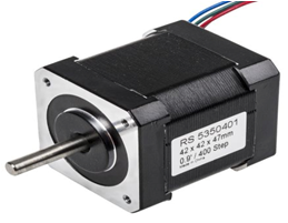
Stepper motor is brushless DC motor, which can be rotated in small angles, these angles are called steps. Generally stepper motor use 200 steps to complete 360 degree rotation, means its rotate 1.8 degree per step. Stepper motor used in many devices which needs precise rotational movement like robots, antennas, hard drives etc. We can rotate stepper motor to any particular angle by giving it proper instructions.

8085 MICROPROCESSOR TRAINER KIT
Specification
Intel 8085A CPU @ 6.144 MHz Clock speed.
RAM : 8KB expandable upto 32KB, Jumper selectable.
EPROM : 8KB expandable upto 32KB, Jumper selectable.
Lithium Battery backup for RAM.
21 Keys multi-function keyboard with double shot characters for long life.
6 digit 7Segment RED LED Display.
3 Channel 16 bit counter / timer terminated in a 10 Pin Connector.
48 TTL I/O Lines, terminated at 26 pin FRC connector
RS232C Compatible serial Port terminated in a 9 Pin "D" Male Connector.
One VXT Bus (50 Pin FRC Connector) for interfacing VBMB series of Experiment boards and bus expansion.
Built-in SMPS Power Supply: Input : 230V AC, Output: +5V / 3.5A, +12V / 150mA.
Built in Line Assembler and Disassembler provided.
Software single stepping of user programs by instruction for software debugging.

HEAT TRANSFER FROM A PIN FIN APPARATUS
DESCRIPTION
The setup is designed to study the heat transfer in a pin fin. It consists of pin type fin fitted in duct. A fan is provided on one side of duct to conduct experiments under forced draft conditions. Airflow rates can be varied with the help of damper provided in the duct. A heater heats one end of fin and heat flows to another end. Heat input to the heater is given through Variac. Digital Temperature Indicator measures temperature distribution along the fin.
STEFAN BOLTZMANN APPARATUS
DESCRIPTION
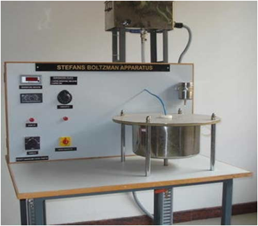
The apparatus is designed to determine the Stefan Boltzman constant.The apparatus consists of a hemisphere fixed to a Bakelite plate, the outer surface of which forms the jacket to heat it.Hot water to heat the hemisphere is obtained form a hot water tank, which is fixed above the hemisphere. The copper test disc is introduced at the center of hemisphere.The temperatures of hemisphere and test disc are measured with the help of temperature sensors.

THERMAL CONDUCTIVITY OF LIQUIDS AND GASES
DESCRIPTION
The Thermal Conductivity of Liquids and Gases Unit has been designed for students to determine the thermal conductivities of various liquids and gases. The unit comes complete with a control panel and a test module which is basically a plug and jacket assembly. With an optional data acquisition system, students shall be able to automatically collect experimental data and perform all the necessary calculations to determine the thermal conductivity of the test liquid or gas.

BERNOULLI'S THEOREM APPARATUS
DESCRIPTION
The equipment is designed and fabricated to demonstrate the Bernoulli's theorem. It consists of a test section made of acrylic. It has convergent and divergent sections. Pressure tappings are provided at different locations in convergent and divergent section. Present set-up is self contained water re-circulating unit, provided with a sump tank, centrifugal pump etc. An arrangement is done to conduct the experiment on different flow rates. Flow rate of water is measured with the help of measuring tank and stopwatch.

IMPACT OF JET ON VANES APPARATUS
DESCRIPTION
The Set-up consists of two sided clear fabr1catt0n. Water is fed through a nozzle and discharged vertically to strike a target carried on a stem, which extends through the cover. A weight carrier is mounted on the upper end of the stem. The dead weight of the moving parts is counter balanced by a Compression spring. The vertical force exerted on the target plate is measured by adding the weights supplied to the weight pan until the mark on the weight pan corresponds with the level gauge. A total of two targets are provided a flat plate and a hemispherical cup.
VENTURI METER & ORIFICEMETER APPARATUS
DESCRIPTION
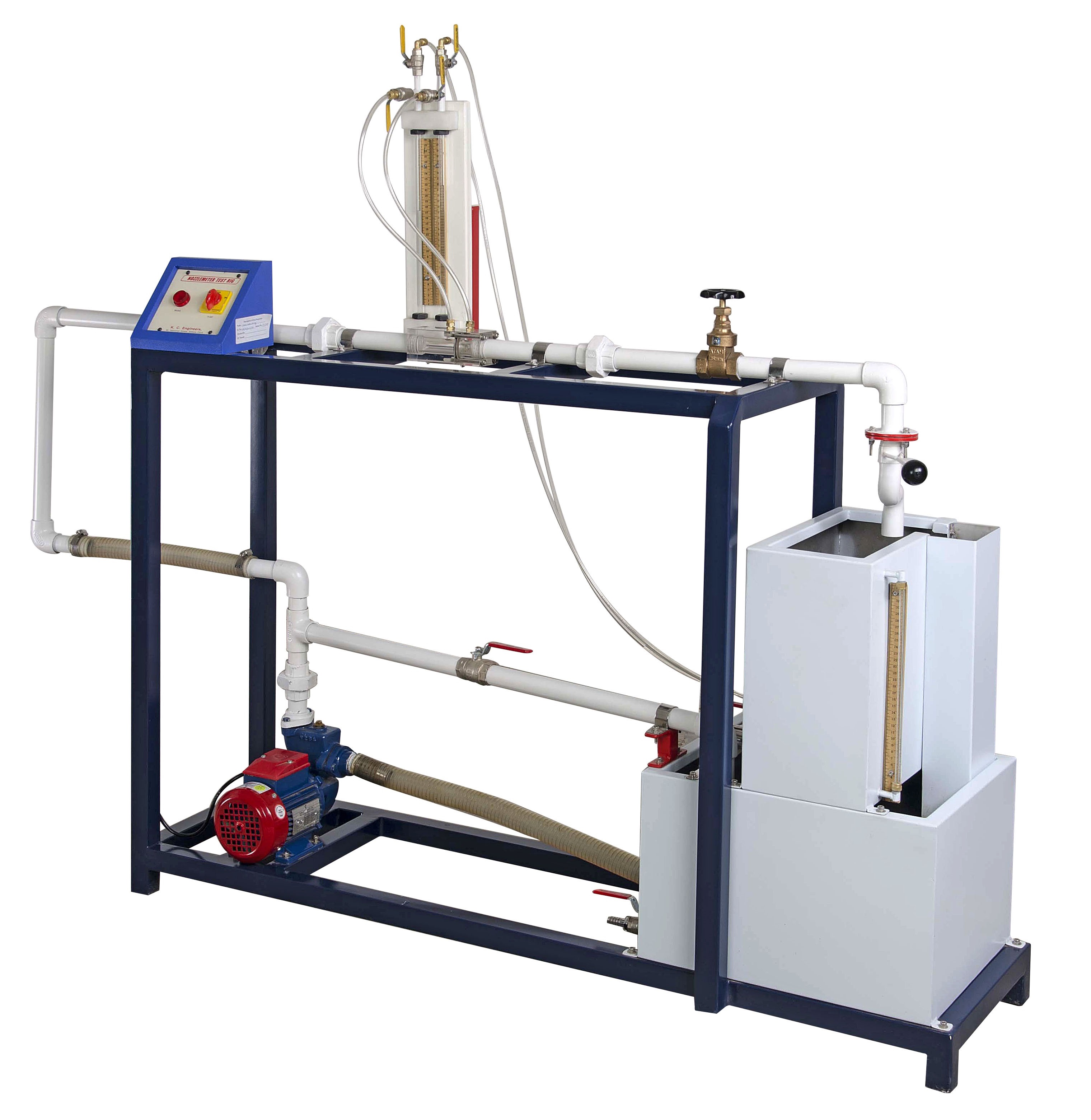
The apparatus consists of two pipelines emerging out from a common manifold. One pipeline contains a Venturimeter, second contains an Orifice. The pressure tapings from the Venturimeter and Orificemeter are taken to differential manometer to measure pressure difference. The Venturimeter and Orificemeter are connected in parallel and anyone of them can be put in operation by operating valves provided at the downstream. These valves can also regulate the flow. Present Set-up is self contained water re-circulating unit, provided with a sump tank and a centrifugal pump. Flow control valve and by-pass valve are fitted in water line to conduct the experiment on different flow rate. Flow rate of water is measured with the help of measuring tank and stop watch.
PELTON WHEEL TURBINE
DESCRIPTION
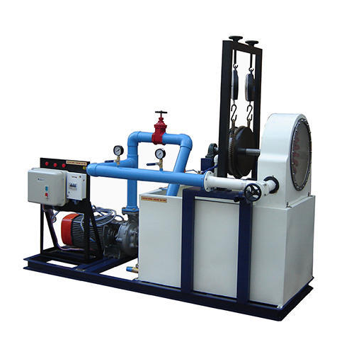
Pelton Wheel Turbine is only impulse water turbine, now in common use, named in the honor of Sir L.A. Pelton (l829· 1908) of California, USA. It is a tangential flow impulse turbine. The water strikes the buckets along the tangent of the runner. The energy available at the Inlet of the Turbine is only kinetic energy. The Pressure at the Inlet and Outlet of the atmospheric. This turbine is used for high heads. The Present Set-up consists of a runner. The buckets are mounted on the runner. The water is fed to the turbine through SS nozzle with a SS spear, by means of Centrifugal Pump, tangentially to the runner. Row of water into turbine is regulated by adjusting the spear position by the help of a given hand wheel. The runner is directly mounted on one end of a central SS shaft and other end is connected to a brake arrangement.
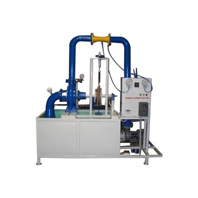
FRANCIS TURBINE TEST RIG
DESCRIPTION
Francis Turbine is a reaction Turbine, which was developed by English born American Engineer Sir J.B. Francis. The water enters the turbine through the outer periphery of the runner in the radial direction and leaves the runner in axial direction and hence it is called a mixed flow turbine. As the water flows to the runner, a part of pressure energy goes on changing into kinetic energy. Thus, the water through the runner is under pressure. The runner is completely enclosed in air tight casing and runner is always full of water.
The present set-up consists of a runner. The water is fed to the turbine by means of centrifugal Pump, radially to the runner. The runner is directly mounted on one end of a central SS shaft and other end is connected to a brake arrangement.

KAPLAN TURBINE TEST RIG
DESCRIPTION
Kaplan Turbine is an axial flow reaction Turbine named in honor of Dr. B. Kaplan. a German Engineer. This turbine is suitable for low head. The power produced by a turbine is proportional to QH. As the head (H) decreases the J discharge (Q) must increase to produce the same power. The present Set-up consists of a scroll casing housing a runner. Water enters the turbine through the stationary guide vanes and passes through the runner axially. The runner has a hub and airfoil vanes, which are mounted on it. The water is fed to the turbine by means of Centrifugal Pump. The runner is directly mounted on one end of a central SS shaft and other end is connected to a brake arrangement. A transparent hollow cylinder made of acrylic is fitted in between the draught tube and the easing for observation of flow on to the airfoil vanes.

GUARDED PLATE APPARATUS
DESCRIPTION
The guarded hot plate apparatus uses a steady-state method in order to determine the thermal conductivity of an insulating material. Use of a steady-state method requires that the insulating material be in equilibrium with its surroundings in order for accurate thermal conductivity measurements to be obtained.
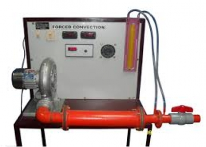
FORCED CONVECTION APPARATUS
DESCRIPTION
The Forced Convection Apparatus is designed to determine heat transfer rate in forced convection. It consists of horizontal copper tube heated by an electric heater. Number of thermocouples are fitted on the surface of the tube along its length. The test pipe is housed inside a steel pipe. A blower provides forced convection of air by blowing the air at high velocity to cause turbulent flow. Flow rate of blower is measured by orifice plate & U Tube Manometer.The control panel consists of a dimmers stat to control the voltage supplied to the heating element. A Voltmeter, an ammeter and a digital temperature indicator are also provided.
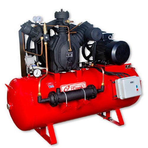
TWO STAGE RECIPROCATING AIR COMPRESSOR
FEATURES:
Designed for continuous duty
Deep finned cast iron cylinders, aluminium cooler tubes ensuring superior heat dissipation for higher operating efficiency
Aero dynamically designed fan with large blades for higher air flow
Efficient cooling to ensure operation at higher ambient temperatures of up to 50°C
Totally enclosed belt guard for utmost safety conforming to Euro norms
Air receiver, conforming to ASME and Euro norms
Optimal distribution of load on cylinders for energy efficiency (Two stage models)
Long life of motor due to no-load starting ensured by built-in unloader
Sturdy, robust cast iron crankcase
Forged steel crankshaft supported at both ends for higher dynamic stiffness and least vibrations
Optimal operating speed for longer service life
Pressure relief valve provided after each stage of compression for safety
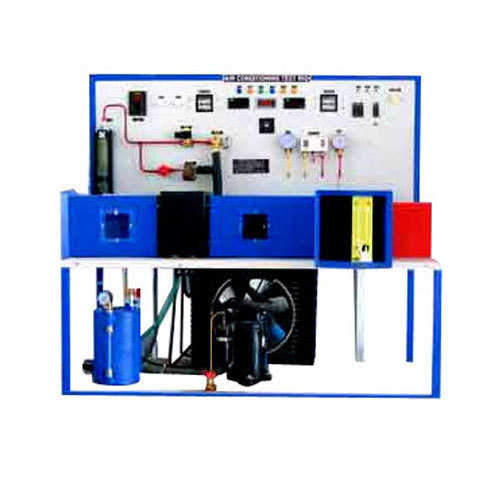
AIR CONDITIONING TEST RIG
Technical Details:
Compressor: Hermitically Sealed Compressor
Capacity 1 Ton, Kirlosker Make
Condenser: Air Cooled Compatible To 1 Ton Compressor
Condenser Cooling Fan: Compatible Capacity With Permanent Lubricated Motor
Pressure Gauges: 2 Nos
Evaporator: Compatible To 1 Ton, Made Of Copper Tube And Aluminium Fins Fitted With Compatible Capacity Fan
Safety Control: Over Load And Over Current Protection For Compressor With Time Delay Circuit
Expansion Device: Capillary Tube Compatible Capacity
Temperature Sensor: Rtd Pt-100 Type
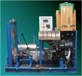
MULTI CYLINDER FOUR STROKE PETROL ENGINE TEST RIG
DESCRIPTION
The Set-up consists of 3/4 Cylinder, 4 Stroke Petrol Engine connected to Dynamometer for engine loading. The Setup has stand-alone type independent panel box consisting of air box, fuel tank, and manometer, fuel measuring unit, digital speed indicator and digital temperature indicator. Engine Jacket cooling water Inlet, Outlet and Calorimeter Temperature is displayed on temperature indicator. Rotameters are provided for cooling water and Calorimeter Flow measurement.

SINGLE CYLINDER FOUR STROKE DIESEL ENGINE TEST RIG
DESCRIPTION
The engine will be sectioned to show the internal constructional details. The working of individual part and accessories like Valves, Pistons, pumps, Crank and Camshaft, etc. will be demonstrated. It is provided with Flywheel and it is mounted on a sturdy iron frame. This actual cut section engine helps the student to understand about the parts and the working of the engine very easily. It is specially made dissectible for demonstration purposes. The actual cut section engine will be supplied with key card & very interesting literature regarding working.
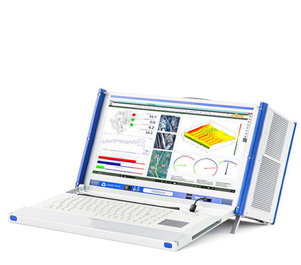
DATA ACQUISITION SYSTEM
Description
Modular construction. A selection of amplifiers tailors the system to address any application.
A range of isolated analog amplifiers support measurements from millivolts to hundreds of volts, as well as thermocouple- and RTD-based temperature measurements.
A logic and pulse input amplifier module provides 16 channels of discrete and/or pulse inputs for state, counting, and rotational rate recording along with analog data.

UNIVERSAL TESTING MACHIN
Description
Universial Testing Machine is designed for testing metals under tension, compression, bending, transverse and shear load, both in the form of test pieces and as finished product (optional). The load is applied by a hydrostatically lubricated ram. The cylinder in turns receives pressure from the power pack. The load is transmitted to the test specimen and is displayed by a separately housed load indicator.

TORSION TESTING MACHINE
Description
Torsion Testing Machine is designed for conducting torsion and twist on various metal wires, tubes, sheet materials torque measurement is by pendulum dyanomometer system.
Torque ranges can be adjusted by auto torque selector.
Torque can be applied to specimen by geared motor through gear box.
Autographic recorder gives the relation between torque and angle of twist.
The accuracy of torque indication is ±1of the true torque.

COMPRESSION TESTING MACHINE
Description
Rugged construction and extreme simplicity makes it possible for even non-technical personnel to operate them with ease and complete dependability. In particular, the portable units, which are small in dimensions, sturdy and light in weight, make quality control testing possible in areas where commercial testing facilities are not available and where the transportation of larger and much heavier machines would be difficult.
Conforms to IS: 14858(2000) and calibrated with an accuracy of± 1 % as per the requirement of 1828(Class1).
It can also be supplied as per BS: 1881 and other associated International Standards.
These machines are available in 50kN, 100kN,500kN, 1000kN,2000kN, 3000kN & 5000kN Capacities.
• Analogue models.
• Digital models with pace rate indicators.
• Micro Controller based models with automatic pace rate controllers.
• Fully Automatic models.
• Servo models.
• Touch Screen Models (Digital, Micro Controller & Automatic)

GOVERNOR APPARATUS
Description
Universal Governor Apparatus is designed to study the working of different governors normally used to control the speed. It consists of a main spindle, mounted vertically on the base plate. This spindle is driven by a variable speed Motor which is also mounted vertically on the same base plate. Any one governor assembly out of four can be mounted on spindle. The spindle speed is controlled by speed control unit. A graduated scale is fitted to the sleeve to measure the displacement.

MOTORIZED GYROSCOPE
Description
The set up consists of stainless steel disc mounted on a horizontal shaft, rotated by a variable speed motor. The rotor shaft is coupled to a motor mounted on a trunion frame having bearings in a yoke frame, which is free to rotate about vertical axis. A weight pan on other side of disc balances the weight of motor. Rotor disc can be move about three axis. Torque can be applied by calculating the weight and distance of weight from the centre of rotor.
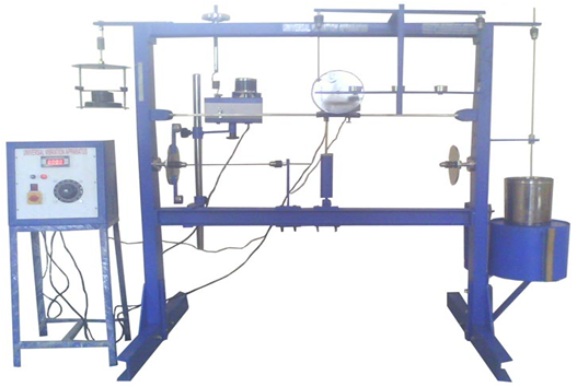
UNIVERSAL VIBRATION APPARATUS
Description
Universal Vibration Apparatus that provides comprehensive unit to perform the vibration experiments. A universal frame is provided upon which quick and easy assembly of various experiments can be done. The unit is self-contained to safely store spares. The students can easily assemble the experiments and study the theory of vibrations practically. We are the prominent producer of efficient and powerful Universal Vibration Apparatus which meet international standard.

STATIC DYNAMIC BALANCING APPARATUS
Description
This equipment is designed for carrying out the experiment for balancing a rotation mass system. The apparatus consists ofa stainless steel shaft fixed in a rectangular frame. A set of four blocks with a clamping arrangement is provided. For static balancing, each block is individually clamped on shaft and its relative weight is found out using cord and container system in terms of number of steel balls. For dynamic balancing, a moment polygon is drawn using relative weights and angular and axial position of blocks is determined. The block are clamped on shaft is rotated by a motor to check dynamic balance of the system. The system is provided with angular and longitudinal scales and is suspended with chains for dynamic balancing.

TOOLMAKERS MICROSCOPE
Description
A hollow base, which accommodates the illumination unit underneath
A circular stage surface (upper part of the base) - It is made of transparent glass and can be rotated 360 degree
An objective lens
Eyepiece
Two micrometer screws (One for longitudinal movement and the other for lateral movement of the stage surface/table)
Ground glass screen
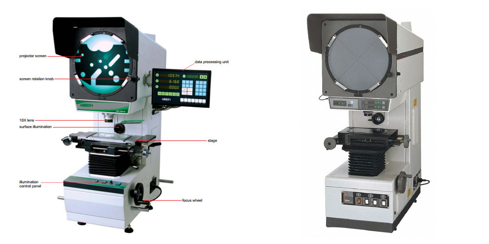
PROFILE PROJECTOR
DESCRIPTION
Profile Projector suitable for all types of measurement & inspections at industries and engineering institutes.
Its multilayer coated projection Objectives provide high transmission & optimum contrast suitable for contour & surface images.
The equipment ensures high accuracy in dimensional measurements and surface inspections.
Its unique rigid pedestal system facilitates vibration free handling of components.
Wide choice of accessories enhances the scope of applications in various fields.
AUTOCOLLIMATOR
Description
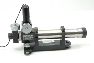
Autocollimator is a Precise Instrument for small angular tilt measurements. Micro-Optic Visual Autocollimator-resolution ranging from 3 arc secs to 0.5 arc secs for Straightness, Squareness, Flatness , Rotary table calibration in Machine Tool Industry. Wide range of Stands and accessories are offered to suit various applications. Autocollimator with camera attachment available with software for Straightness & Flatness or machine Geometry measurements.
VICKERS HARDNESS TESTER
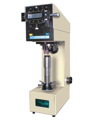
Features :
Testing range is very wide, from soft metal such as lead, upto the hardest, like hardeness steel.
Same hardness number is obtained on the same specimen, regardless of the load applied.
The indication is tiny and allows testing of a precision finished part.
Loading and unloading cycle is motorised.
Thin sheet metal is perfectly tested because the load applied is very small.
Built-in projection screen to get accurate results.

ROCKWELL HARDNESS TESTER
Description
Rockwell & Rockwell Superficial tests consists of forcing an indentor (Diamond or Ball) into the surface of a test piece in two steps i.e. first with preliminary test force and thereafter with additional test force and then measuring depth of indentation after removal of additional test force (Remaining preliminary test force active) for measurement of hardness value.

BRINELL HARDNESS TESTER
Description
Machine designed with a hydraulic power pack and control circuit for effortless loading unloading operation. A dial gauge in front measure depth of ball penetration. This facilites production testing within tolerance limits by compression method.
These machines are designed to measure hardness of castings, forgings, other metals and alloys of all kinds, hard or soft, whether flat, round or irregular in shape.
